TUTORIAL - PART 2
9) Since there are so few parts specified for LTE or HTE, how does one build hardware?
The availability and range of parts specified by vendors for extreme-temperature operation is limited, and changes from year to year. Thus, finding suitable parts is one of the major difficulties facing those who want to make LTE or HTE hardware. The underlying problem is that LTE and HTE represent a very small, and often difficult, market.
To obtain the parts needed to complete a piece of LTE or HTE hardware, there have been two main approaches: (1) qualify conventional ("commercial-off-the-shelf" or COTS) parts, or (2) have custom parts made. Choosing between these involves a number of factors, including the budget, performance requirements, criticality of the application, and closeness of commercial parts to the required characteristics. Each approach has is advantages and drawbacks.
Using existing commercial parts is generally less expensive and faster than having custom parts made. Components specified for conventional temperatures are often used for LTE and HTE. The typical procedure is to buy batches of parts made by different vendors and test them for functionality and reliability for the operating conditions of the intended application. This is generally more difficult for HTE because parts can degrade rapidly and lifetime needs to be established.
However, there may be no commercial part that meets, or comes close to, the user's requirements. Moreover, since these parts are not specified for operation at temperatures outside the conventional range, the manufacturer has no obligation to maintain their characteristics at extreme temperatures. Consequently, a problem often encountered is that after a suitable part has been found, the manufacturer may change the fabrication of the part such that it still meets the specifications for conventional use but the characteristics at low or high temperature are significantly altered.
Custom parts can be made to meet extreme-temperature requirements to a lesser or greater degree, depending on the time and expense. This approach has been used for critical applications that can justify the time and expense. However, the number of organizations that are willing to undertake making a part for low- or high-temperature operation is limited. Moreover, these organizations can change their areas of business and discontinue the service.
10) If one plans to use conventional commercial parts for LTE of HTE, how does one begin selecting them?
Guidelines for selecting parts have emerged over the years, based on fundamentals and experience, but finding parts that work outside their specified temperature range still involves considerable trial and error.
First, it is important to think about the application: How critical is it? How serious is a failure? How long does the electronics have to operate at the low or high temperature (hours or years)? How easy is it to replace a part or a circuit? These factors have to be traded off against the time and expense of qualifying parts. For example, an HTE system in an airplane warrants considerably more effort on parts qualification compared to an HTE circuit used in a laboratory experiment.
Next, it is important to consider the intended application. Basic questions are how much change in characteristics can be tolerated and whether there are ways to compensate or reduce the effects of the change. There will always be some change with temperature. For critical parts even a small (say ~1%) variation may be too great, while for other uses even a large variation may not matter. Also, how long must the part remain within a certain specification at the extreme temperature—in other words, how much aging can be tolerated? This question usually applies to HTE, but can also arise for LTE. Aging can have a complicated dependence on time and temperature because there are often several mechanisms with different temperature dependencies active at the same time.
Basic materials properties also need to be considered, since these can limit the temperature capability of a part. This is mainly an issue for HTE, but also arises for LTE. For example, solders should not be used at temperatures above their melting point, or even near it, because they lose strength rapidly as the temperature approaches their melting point. At the other extreme, some solders, especially those with high Sn content, are not advisable for LTE use because they become brittle [1]. Plastics also have an upper temperature rating, above which they deteriorate rapidly. In addition, plastics have a glass transition temperature at which their properties change significantly. Plastics vary in their suitability for low-temperature use as well.
Thus, when considering a component for HTE or LTE that incorporates solders or plastics (including adhesives), the temperature limitations of these materials should be kept in mind. Other materials such as ceramics, glasses and metals (other than solders) usually do not present a problem in themselves for LTE or HTE operation. However, at high temperatures there are concerns about interactions of materials. A notorious example of this is the interaction of aluminum and gold in wirebonding, which can take place at relatively low temperatures (~150°C) even though the materials in themselves can withstand much higher temperatures.
Another general guideline is to favor parts that are specified for the "military" temperature range (−55°C to +125°C) as these are more likely to withstand a wider operating temperature.
11) How do the characteristics of components change at extreme temperatures?
This is a complex matter that cannot be answered in a few words. The following are a few basic observations.
There are many electronic, ionic, and atomic processes taking place in a component. Some of these determine its characteristics at "conventional" temperatures, but there are others that may come into play at higher or lower temperatures to introduce new effects, either gradually or abruptly. The trends in characteristics exhibited by components over the conventional temperature range often continue to higher and lower temperatures. However, extrapolation is risky because there may be some "critical" temperature at which the component undergoes an abrupt change in characteristics. Examples of this are the freeze-out temperature of Si (about −230°C/40 K) below which there are major changes in a Si device's characteristics.
At low temperatures, the most difficulty arises with components that rely on movement of ions or on chemical processes. These include electrolytic capacitors, some types of ceramic capacitors, and batteries. At low temperatures such activity "freezes out." Electrolytic capacitors typically lose capacitance rapidly upon cooling, and at cryogenic temperatures (below about −150°C) may have perhaps 10% of their room-temperature capacitance.
Batteries for low temperatures are also problematical. I know of no battery that operates below about
−100°C. Independent power sources that can operate at very low temperatures are lacking; consequently, power for cryogenic electronics must be fed in from a "warm" region. The most common method is through wires, although optical (or even mechanical) methods are alternatives. At high temperatures the situation is somewhat better, batteries are available for up to ~200°C [2].
Information on resistors and capacitors appears below. Semiconductor devices are much more complicated; descriptions of their behavior are planed for subsequent Tutorials.
12) How do passive components behave at extreme temperatures?
There are considerable data for passive components at high temperatures, but relatively little for low temperatures. Following are some general remarks on the more common types of resistors and capacitors [3].
Resistors:
Thin-film and metal-film resistors, such as Ni-Cr, Ta2N/Ta-N, and Cr-Si generally behave very well at low
temperatures. At high temperatures behavior varies, but they have been used to 200°C, although aging may be a problem at temperatures
above about 200–250°C.
Thick-film resistors vary in their behavior at low temperature: some types change resistance by only a few percent, while others
may exhibit large changes. They have good stability for high-temperature use and have been characterized to 500°C with reasonable
results (for example, see the figure below). They also appear to have good aging characteristics up to 300°C. Thick-film resistor formulations have been developed for high-temperature use.
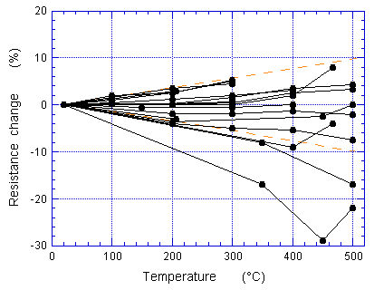
Thick-film resistor behavior.
Copyright © 1999 IEEE. Reprinted from Part VII of High-Temperature Electronics, ed. R. Kirschman, IEEE Press, 1999.
This material is posted here with permission of the IEEE [3].
Carbon resistors, which have a more complex conduction mechanism, usually exhibit a large change with resistance at low temperature.
In fact, they have been used as cryogenic temperature sensors. Use at high temperatures is questionable.
In regard to resistor power ratings, it will likely be necessary to derate for high-temperature use; also, at low temperature power
dissipation may need to be limited to avoid an excessive burden on the cooling system.
Capacitors:
Capacitors with polymer (plastic) dielectrics seem to behave well at low temperatures. For high-temperature use they are generally
limited to about 200°C, although fluoropolymers and some other polymeric materials should be useable to a somewhat higher temperature. Their capacitance usually does not change much with temperature, low or high.
Ceramic capacitors are suitable for both low and high temperatures to at least 300°C. They vary in their behavior. The
low-to-medium dielectric-constant types, such as COG and NPO exhibit a relatively small change in capacitance at low or high temperatures.
In contrast, high dielectric-constant types, such as XR7 and Z5U, have more complex dielectric materials and can lose a major portion of their capacitance at low or high temperature (see the figure below).
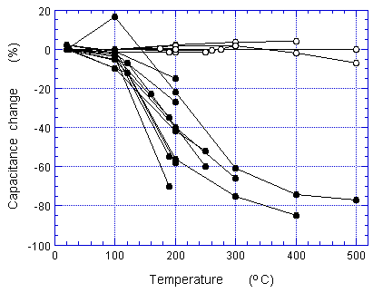
Ceramic capacitor behavior: open circles are low/medium dielectric
constant, solid circles are high dielectric constant. Copyright © 1999 IEEE. Reprinted from Part VII of High-Temperature
Electronics, ed. R. Kirschman, IEEE Press, 1999. This material is posted here with permission of the IEEE [3].
Electrolytic capacitors (solid electrolytic) also can exhibit large changes in capacitance at low or high temperatures. At low
temperature they generally lose a major portion of their capacitance. At HT their capacitance can increase substantially; aluminum electrolytics
appear to be somewhat better than tantalum electrolytics.
At high temperature insulation resistance decreases substantially and breakdown voltage generally decreases. Capacitors used for power
applications may need considerable derating in ac capability because of increased internal losses and heat generation.
To use a component above its rated temperature, it may be possible or necessary to trade-off some other parameter. As mentioned, for
resistors the allowable power dissipation may need derating (in other words, use a larger resistor than for the equivalent conventional-temperature case). For capacitors the voltage may need derating (use a higher-voltage capacitor), and so forth.
[1] For details on solder behavior at low temperatures and a discussion on thermal expansion see: R. K. Kirschman, W. M. Sokolowski,
and E. A. Kolawa, "Die Attachment for −120°C to +20°C Thermal Cycling of Microelectronics for Future Mars
Rovers – An Overview," J. Electronic Packaging, vol. 123, pp. 105-111, June 2001
(http://trs.jpl.nasa.gov/handle/2014/17025).
An earlier version was published in Advances in Electronic Packaging – 1999, EPP Vol. 26-2, pp. 1399-1405
(proceedings of the Pacific Rim/ASME International Intersociety Electronic Packaging Conference InterPACK '99).
[2] For further information on batteries and high temperatures see the article by W. Clark in High-Temperature Electronics, ed. R. Kirschman.
[3] Internal or personal use of this material is permitted. However, permission to reprint/republish this material for advertising or promotional purposes or for creating new collective works for resale or redistribution must be obtained from the IEEE by sending a blank email message to pubs-permissions@ieee.org. By choosing to view this document, you agree to all provisions of the copyright laws protecting it.
The preceding has been adapted from the Extreme-Temperature Electronics Newsletter Issue #2 (26 June 2001). The coverage is abbreviated and many points are only touched on. Further information may be obtained from the included Internet links and from the items
listed separately.
Return to top of page
¦ Part 1
¦ Part 3
¦ Part 4
Home
Most recent update: 23 November 2021
Copyright © 2001, 2002, 2003, 2006, 2021 by Randall K. Kirschman. All rights reserved.
